Elektronik
Willkommen auf unserer Elektronik Wiki Seite
Inhaltsverzeichnis
- 1 Shops
- 2 Elektronik-Kompendium
- 3 Webseiten
- 4 Bauteile Passiv
- 5 Das Elektronik-Labor
- 6 Fritzing
- 7 EleLa - Elektronik Lagerverwaltung ab V2.0
- 8 Sunfounder
- 9 sms-guard
- 10 CAN Bus
- 10.1 MCP2515 CAN Bus Modul - TJA1050 Transceiver 5V Arduino Raspberry Pi
- 10.2 NEU SN65HVD230 CAN bus transceiver communication module For Arduino de
- 10.3 SN65HVD230 CAN Board Network Transceiver Evaluation Development Module
- 10.4 High Speed Bus Interface Protocol Controller MCP2551 Can Communication Module
- 11 NE555
- 12 RFID
- 13 USB
- 14 Messgeräte
- 14.1 Funktionsgenerator IC-XR2206 als Bausatz
- 14.2 FR4+Acryl Signal Generator DIY-Kit LCD-Anzeige Vorwärtswelle Funktion Praktisch
- 14.3 PWM Board Module Pulse Frequency Duty Cycle Adjustable Module LCD Display
- 14.4 DIY Kits NE555 Multi-Channel Waveform Generator Suite For Electronic Experiment
- 14.5 DSO 138Mini Osziloscope Bausatz
- 14.6 Bauteil Tester GM328
- 15 SMD
- 16 Löten
- 17 Bauteile
- 17.1 Slide Potentiometer 10K Linear Module Dual Output
- 17.2 Rotary Encoder EC12 Audio Digital Potentiometer 15mm Handle
- 17.3 LED
- 17.4 Displays
- 17.5 Pegelwandler 5V 3,3V 4Kanal Level Shifter
- 17.6 TSOP1136 IR-Empfänger
- 17.7 TSOP 4838 IR-Empfänger
- 17.8 Fernbedienung + HX1838 Empfänger + Codiert Infrarot modul
- 17.9 SPI
- 17.10 I2C
- 17.10.1 PCF 8566
- 17.10.2 PCF 8570
- 17.10.3 PCF 8573
- 17.10.4 PCF 8574 P I2C Port Expander
- 17.10.5 PCF 8582
- 17.10.6 PCF 8584 I2C-bus Controller
- 17.10.7 PCF 8591
- 17.10.8 YL-40 PCF8591 8 Bit Analog-Digital-Wandler ADC I2 C YL-40 Arduino
- 17.10.9 DS 1620
- 17.10.10 EEProms 24C02
- 17.10.11 PN532 NFC RFID
- 17.10.12 OLED Display
- 17.10.13 TM1638 LED&Key
- 17.10.14 DS3231 AT24C32 IIC Modul Präzisions-Taktmodul
- 17.10.15 ZS-042 Real-time Clock Module - Blau DS3231
- 17.10.16 SRF 08 Ultraschall Abstandssensor
- 17.10.17 HC-SR04 Ultraschall Abstandssensor
- 18 Module
- 18.1 MINI L293D Arduino Motorantrieb Erweiterungskarte Mini L293D Motorantrieb Modul
- 18.2 GY-68 BMP180 I2C Digitaler Luftdrucksensor Board
- 18.3 3 in 1 Remote Control + HX1838 Receiver + Coded Infrared Module with Female to Female Dupond Line Wire Cable Free Shipping
- 18.4 HC-SR501 Body Sensor Module Adjust IR PIR Pyroelectric Infrared PIR Motion Human Sensor Detector Module For Arduino
- 18.5 BV4221
- 18.6 RS232-TTL
- 18.7 HC-05
- 18.8 BlueSmirf
- 18.9 RFM12
- 18.10 Tastenfeld
- 18.10.1 Arduino Keypad Pinout
- 18.10.2 3x4
- 18.10.3 TTP224 4 Schlüssel Buttons Touch-Switch-Modul Touch-Kapazität Digital-Wandler Vorstand Sensor 2,4V-5,5V
- 18.10.4 TTP226 8-Kanal-kapazitiver Schalter Digital Touch Sensor Board-Modul für Arduino
- 18.10.5 TTP229 16-Channel Digitaler Touch Kapazitiver Sensor Modul XD-62B TTP229
- 18.10.6 4x4
- 18.10.7 Folientastatur mit i2C Portexpander PCF8574
- 18.10.8 ESP Easy Tastatur und PCF8574
- 18.10.9 I2C
- 19 Sensoren
- 19.1 50 DER WICHTIGSTEN RASPBERRY PI SENSOREN UND MODULE
- 19.2 Infrared Reflective Photoelectric Switch TCRT5000 Ir Barrier Line Track Senso io
- 19.3 YL-40 PCF8591 8 Bit Analog-Digital-Wandler ADC I2 C YL-40 Arduino
- 19.4 Luftdruck HP03S I2C
- 19.5 Luftfeuchte HH10D
- 19.6 DHT11 / DHT22 AM2302
- 19.7 GY-68 BMP180
- 19.8 3 Achsen Beschleunigung MEMS1
- 19.9 GY-521 3 Achsen MPU-6050 Beschleunigungssensor / Gyroskop / Accelerometer
- 19.10 X9C103S Digital Potentiometer Board Module DC3V-5V for Arduino 10K Span Potentiometer
- 19.11 Kompassmodul HDMM01
- 19.12 Flexsensor 2.2
- 19.13 37-IN-1-SENSOR-KITS-FOR-ARDUINO
- 19.13.1 Arduino
- 19.13.2 RaspBerryPi
- 19.13.3 KY-001 DS18B20
- 19.13.4 KY-002
- 19.13.5 KY-003
- 19.13.6 KY-004 Button
- 19.13.7 KY-005
- 19.13.8 KY-006 Buzzer
- 19.13.9 YL-44
- 19.13.10 KY-007
- 19.13.11 KY-008 Laser
- 19.13.12 KY-009 3C LED
- 19.13.13 KY-010
- 19.13.14 KY-011
- 19.13.15 KY-012
- 19.13.16 KY-013
- 19.13.17 KY-014
- 19.13.18 KY-015 Temp/Hum
- 19.13.19 KY-016
- 19.13.20 KY-017
- 19.13.21 KY-018 FotoR
- 19.13.22 KY-019 Relay
- 19.13.23 KY-020
- 19.13.24 KY-021
- 19.13.25 KY-022
- 19.13.26 KY-023
- 19.13.27 KY-024 Linear magnetic Hall Sensor
- 19.13.28 KY-025
- 19.13.29 KY-026
- 19.13.30 KY-027
- 19.13.31 KY-028
- 19.13.32 KY-029
- 19.13.33 KY-030
- 19.13.34 KY-031
- 19.13.35 KY-032
- 19.13.36 KY-033
- 19.13.37 KY-034
- 19.13.38 KY-035
- 19.13.39 KY-036
- 19.13.40 KY-037
- 19.13.41 KY-038
- 19.13.42 KY-039
- 19.13.43 KY-040 Rotary Encoder
- 19.13.44 WIKI
- 19.14 Gas Sensoren MQ
- 19.15 Pulsesensor
- 19.16 Sensormodul Regen Wetter Modul
- 19.17 Feuchtigkeitssensor
- 19.18 SHARP IR Ranger Sensor GP2D12
- 19.19 Fingerprint Sensor
- 19.20 GP2Y1014AU0F Compact Optical Dust Sensor
- 20 Spannungsversorgungen
- 20.1 DC 5-24V to Dual Power ±12V ±5V +3.3V Boost USB Linear Regulator Module DIY Kit
- 20.2 Spannungsversorgung 5V/3,3V
- 20.2.1 Power
- 20.2.2 MB102
- 20.2.3 TSP 03
- 20.2.4 TSP 05
- 20.2.5 5V 700mA 3.5W
- 20.2.6 2PCS Ultra-small LM2596 power supply module DC / DC BUCK 3A adjustable buck module regulator ultra LM2596S 24V switch 12V 5V 3V
- 20.2.7 Mini Buck Step Down Converter DC-DC 1.2V 2.5V 3V 3.3V 5V Power Supply Module
- 20.2.8 AC 220V 230V to DC 3.3V 5V 9V 12V Step Down Converter Board Power Supply Module
Shops
https://eckstein-shop.de/
https://www.ramser-elektro.at/shop/
https://www.muekra.de/
https://www.funduinoshop.com/
Elektronik-Kompendium
https://www.elektronik-kompendium.de/
Webseiten
http://www.afug-info.de
Bauteile Passiv
Kondensator
Kennzeichnung Kondensatoren
https://www.elektronik-kompendium.de/sites/bau/1109061.htm
http://www.jukebox-world.de/Forum/Archiv/FAQ-Technik/Kondensator.htm
BreadBoard
25 Polig

55 Polig

Das Elektronik-Labor
Fritzing
EleLa - Elektronik Lagerverwaltung ab V2.0
Sunfounder
sms-guard
CAN Bus
MCP2515 CAN Bus Modul - TJA1050 Transceiver 5V Arduino Raspberry Pi

Vollfertiges CAN-Bus Modul zum Betrieb z.B. an Arduino oder Rapsberry Pi per SPI Schnittstelle.
Technische Daten:
Betriebsspannung: 5V
Logikspannung: 5V
Chip: MCP2515|TJA1050
SPI – 10MHz
CAN 2.0B
NEU SN65HVD230 CAN bus transceiver communication module For Arduino de

nd high quality!
SN65HVD230 can be used under high interference environment.
The device has the ability to send and receive good at different rates,
Fully compatible with ISO11898 standard;
High input impedance, allowing 120 nodes;
Low current standby mode, the typical current of 370μA;
Signal transfer rate up to 1Mb / s;
Thermal protection, open circuit failure protection function;
With anti-instantaneous interference protection bus;
Slope control, reduce radio frequency interference (RFI);
Differential receiver with a wide range of anti-common-mode interference,
electromagnetic interference (EMI) capabilities.
Specifications:
Operates With a 3.3V Supply
Color: Blue
SN65HVD230 CAN Board Network Transceiver Evaluation Development Module

The SN65HVD230 CAN Board is an accessory board features an onboard CAN transceiver SN65HVD230, which is pinout compatible with PCA82C250. It is powered from 3.3V and features ESD protection.
The SN65HVD230 CAN Board is ideal for connecting microcontrollers to the CAN network.
Specifications:
Material:PCB
Color:Blue
Size:38x11x10mm/1.49x0.43x0.39 Inch
Weight:3g
High Speed Bus Interface Protocol Controller MCP2551 Can Communication Module

MCP2551 is a fault-tolerant, high-speed CAN devices can be used as CAN protocol controller and the physical bus interface. MCP2551 provides differential receive capability to the CAN Protocol controller, which is fully in line with ISO-11898 standards, including energy 24V requirements.
Typically, each node on the CAN system must have a device, the digital signal is converted into CAN controller generates a signal for bus transport. It also provides high voltage spikes between CAN controller and CAN bus joined the buffer, these high-pressure spikes may be generated by an external device.
Support 1MB / S's run rate.
Meet the ISO-11898 standard physical layer requirements.
Suitable for 12V and 24V systems. Slope external control, reduce RFI.
Automatic detection TXD input ground fault.
Power-on reset and voltage brown-out protection.
Unpowered node or Brown will not affect CAN bus.
Low current standby operation.
Up to 112 nodes can be connected
NE555
http://www.elektronik-kompendium.de/sites/bau/0206115.htm
https://www.elektronik-kompendium.de/sites/slt/0310131.htm
http://www.kreatives-chaos.com/artikel/ne555-grundschaltungen
http://houseofjeff.com/555-timer-oscillator-frequency-calculator/
https://de.wikipedia.org/wiki/NE555

NE555 Adjustable Frequency Pulse Generator Modul NE555

RFID
RFID-RC522


Willkommen auf der RFID Wiki Seite
http://air.imag.fr/index.php/RFID-RC522_RF_IC_Card_Sensor_Module_203517
http://www.nxp.com/documents/data_sheet/MFRC522.pdf
RaspberryPi

Webseiten
http://www.nikolaus-lueneburg.de/2014/06/rfid-rc522-modul-mit-spi-schnittstelle/
http://www.elli-blog.de/?p=41
https://github.com/mxgxw/MFRC522-python/blob/master/Read.py
http://geraintw.blogspot.de/2014/01/rfid-and-raspberry-pi.html?showComment=1422882869378#c6295757221222802715
http://tutorials-raspberrypi.de/raspberry-pi-rfid-rc522-tueroeffner-nfc/
Einrichtung
Download aktuelles Image
https://www.raspberrypi.org/downloads
Konfiguration
sudo /usr/bin/raspi-config
Hostname ändern
Internationale Einstellungen ändern
I2c aktivieren
SPI aktivieren
Installieren XRDP
sudp apt-get install xrdp
I2C / SPI
sudo nano /etc/modules
i2c-dev
i2c-bcm2708
spi-bcm2708
sudo nano /etc/modprobe.d/raspi-blacklist.conf
#blacklist spi-bcm2708
#blacklist i2c-bcm2708
blacklist snd-soc-pcm512x
blacklist snd-soc-wm8804
Device Tree
Eleganter ist es, einen schnittstellenspezifischen Parameter in der Datei /boot/config.txt einzutragen. Normlalerweise sind die Schnittstellen durch ein Kommentarzeichen (#) deaktiviert:
#dtparam=i2c_arm=on
#dtparam=i2s=on
#dtparam=spi=on
Modul Installation
# sudo apt-get install python-dev
# sudo apt-get install gcc
# git clone https://github.com/lthiery/SPI-Py
# cd SPI-Py
#  sudo python setup.py install
# git clone https://github.com/mxgxw/MFRC522-python
# cd MFRC522-python
# sudo python Read.py
Arduino

Pin Belegung
 SS or SDA > Pin 10
 SCK > Pin 13
 MOSI > Pin 11
 MISO > Pin 12
 IRQ
 Ground > Ground
 Reset > Pin 5
 3.3v > 3.3v
How to get started with the Mifare MF522-AN and Arduino
https://github.com/miguelbalboa/rfid
Code RFID testen
 #include <SPI.h>
 #include <MFRC522.h>
 #define SS_PIN 10
 #define RST_PIN 5
 MFRC522 mfrc522(SS_PIN, RST_PIN);
 void setup()
 {
 Serial.begin(9600);
 SPI.begin();
 mfrc522.PCD_Init();
 Serial.print("Start RFID");
 }
 void loop()
 {
 if ( ! mfrc522.PICC_IsNewCardPresent())
 {
 return;
 }
 if ( ! mfrc522.PICC_ReadCardSerial())
 {
 return;
 }
 Serial.print("Die ID des RFID-TAGS lautet:");
 for (byte i = 0; i < mfrc522.uid.size; i++)
 {
 Serial.print(mfrc522.uid.uidByte[i], HEX);
 Serial.print(" ");
 }
 Serial.println();
 }
http://playground.arduino.cc/Learning/MFRC522
http://www.instructables.com/id/Arduino-RC522-RFID-Door-Unlock/
http://www.instructables.com/id/Arduino-RFID-Reader-MFRC522-Turorial/
http://arduino-er.blogspot.de/2015/10/arduino-uno-rfid-rc522-mfrc522-library.html
http://funduino.de/index.php/3-programmieren/nr-19-rfid
http://fluuux.de/2015/08/eine-tuer-mit-rfid-chip-oeffnen-rfid-rc522/
https://www.loxforum.com/forum/faqs-tutorials-howto-s/21162-rfid-reader-arduino-ethernet-rc522
https://electricalkida.blogspot.com/2019/03/esp-32-with-rfid-mfrc522-1-you-download.html
Homematic
http://www.forum-raspberrypi.de/Thread-rfid-rc522-und-homematic
FHEM
lesen von Werten
http://192.168.0.44:8083/fhem&cmd=%7BValue%28%22RFIDTest%22%29%7D&XHR=1
Python
import urllib
sock = urllib.request.urlopen("http://diveintopython.org/")
htmlSource = sock.read()
sock.close()
print (htmlSource)
setzen von Werten
http://192.168.0.44:8083/fhem&cmd.RFIDTest=set%20RFIDTest%20 ON / OFF
http://192.168.0.44:8083/fhem&cmd.RFIDTest=set%20RFIDTest%20SN%20xx123456
Python
import urllib
urllib.urlretrieve('http://192.168.0.1:8181/x.exe?Antwort=dom.GetObject("BidCos-RF.IEQ0012345:1.STATE").State(1)')
RFID PN532 Mini Breakout Modul

http://www.nikolaus-lueneburg.de/2016/03/rfid-pn532-mini-breakout-modul/
ESPEASY PN532
https://www.letscontrolit.com/wiki/index.php/PN532
Arduino RFID Reader mit ID-12LA
http://www.nikolaus-lueneburg.de/2015/05/arduino-rfid-reader-id-12la/
USB

Messgeräte
Funktionsgenerator IC-XR2206 als Bausatz
http://www.normei-weinheim.de/Oszillo/XR2206-Bausatz_V1.htm
http://www.ak-modul-bus.de/stat/funktionsgenerator_bausatz_xr2206_kit,pd0,,XR2206-KIT.html


FR4+Acryl Signal Generator DIY-Kit LCD-Anzeige Vorwärtswelle Funktion Praktisch


Features:
Uses ICL8038 and high-speed op amp, higher accuracy.
Can output sine/triangle/square/forward and reverse sawtooth waveforms.
LCD display to indicate the data accurately.
Frequency Range: 5Hz~400kHz; Duty Cycle Range: 2~95%(Adjustable)
Adjustable frequency and amplitude.
Supports dual power amplifier without blocking the capacitor to ensure high and low frequency signal distortion.
Frequency adjustment features coarse tuning and fine tuning.
All are through hole components, easy to install.

Specification:

Material: FR4 + Acrylic
Supply Voltage: 12V~15V
Frequency Range: 5Hz~400KHz(Adjustable)
Duty Cycle Range: 2~95%(Adjustable)
Low Distortion Sine Wave: 1%
Low Temperature Drift: 50ppm / °C
Output Triangular Wave Linearity: 0.1%
DC Bias Range: -7.5V~7.5V
Output Amplitude Range: 0.1V~11VPP(operating voltage 12V)
Board Dimension: 7.8*5cm/3.07*1.97 inch (Approx)
Finished Product Dimension: 8.7*6*1.7cm/3.43*2.36*0.67 inch (Approx)
PWM Board Module Pulse Frequency Duty Cycle Adjustable Module LCD Display

2-way 5-30v
Highlights:
Two independent PWM generators can set the frequency, duty cycle;
The wide frequency range, high accuracy;
Can serial communication.

First, the module description:
Frequency is divided into three ranges:
XXX (no decimal point): the smallest unit is 1Hz, the range 1Hz ~ 999Hz;
XX.X (decimal point in ten): The minimum unit is 0.1Khz; the range of 0.1KHz ~ 99.9KHz
X.X.X. (there are three decimal point): the smallest unit is 1Khz; the range 1KHz ~ 150KHz
Frequency display example:
""100"" indicates that the PWM output pulse of 100Hz;
""54.1"" indicates that the PWM output pulse of 54.1KHz;
""1.2.4."" Indicates that the PWM pulse output 124KHz
Duty Cycle in the range: 0 to 100;
Three frequencies duty cycle is the same, all the parameters non-volatile.

Second, the module parameters:
Working voltage: 5--30V, support micro USB 5.0V power supply;
Frequency range: 1Hz ~ 150KHz;
The frequency accuracy: ± 2%;
Output Current: Output amplitude: Default 5Vp-p (settable);
Operating temperature range: -30 ~ + 70 ℃.

Third, the parameter settings:
Module has three buttons [Set], [Up], [Down];
Press [Set] key to switch the display four parameters (FR1: PWM1 frequency; dU1: PWM1 duty cycle; FR2: frequency of PWM2; dU2: PWM2 duty cycle), before the handover parameters, there will be corresponding parameter name flash.
Press [Up], [Down] keys to modify the current parameter value (long press can quickly add or subtract fast).
Two PWM each have three preset frequency, the frequency display interface, long press [SET] key to switch between three types of frequencies, three kinds of frequency duty cycle is the same value. (XXX: range 1Hz ~ 999Hz; XX.X: range 0.1Khz ~ 99.9Khz; X.X.X .: range 1Khz ~ 150Khz,).

Fourth, the scope:
As square wave signal generator which generates a square wave signal;
to provide a signal to the stepping motor driver;
Adjustable pulse generation for chip use;
produce variable pulse signal, the control-related circuit (PWM dimming, speed).

Fifth, the serial Control
Baud rate: 9600 bps
Data bits: 8
Stop bits: 1
Parity bit: None
Flow control: none
1, set the PWM frequency
""S1FXXXT"": setting PWM1 frequency of XXX HZ (001 ~ 999)
""S1FXX.XT"": set the frequency of PWM1 XX.X KHZ (00.1 ~ 99.9)
""S1F: X.X.X.T"": setting PWM1 frequency of XXX KHZ (0.0.1 ~ 1.5.0..)
'S1': PWM1
'S2': PWM2
'F': Frequency
'D': Duty Cycle
'T' is the end flag
Set the PWM duty cycle
""S1DXXXT"": setting PWM1 duty cycle XXX; (001 ~ 100)
""S2DXXXT"": set PWM2 duty cycle XXX; (001 ~ 100)
Setting successful return: DOWN;
Setting failback: FALL.
NO Retail Box. Packed Safely in Bubble Bag.
Package Included:
1 x 2 way Independent PWM Generator"
DIY Kits NE555 Multi-Channel Waveform Generator Suite For Electronic Experiment

DSO 138Mini Osziloscope Bausatz
https://jyetech.com/forum/viewforum.php?f=1
https://jyetech.com/dso138mini-oscilloscope-diy-kit/
https://www.youtube.com/watch?v=RapnTtLNI1Y


SMD Teile Mini Digitaloszilloskop Bausatz +klarer Fall Vorgelötet Beliebt
Features:
* 2.4-inch color TFT LCD with 320x240 resolution displays parameters clearly.
* Can be connected with computer for data transmission.
* Making MCU and LCD stay in one PCB to avoid problematic pin-header connections.
* It can work on USB or a single cell 3.7V Li-ion battery.
* Can freeze at any time waveform display (HOLD function).
* With auto/normal/single trigger modes, easy to capture the moment waveform.
* Rising or falling edge trigger.
* Observable previous trigger waveform (negative delay).
* Short-circuit and open-circuit detection and TFT controller recognition.
* With waveform storage function.
Specifications:
* Display: 2.4" Color TFT LCD with 320*240 Resolution
* Number of Channel: 1
* Trigger Modes: Auto, Normal, and Single
* Trigger Position: Center of Buffer
* Supply Voltage: DC 3.5V - 5V
* Current Consumption: 120mA @ 5V
* Analog Bandwidth: 0-200KHz
* Sensitivity Range: 10mV/Div - 5V/Div
* Sensitivity Error: <5%
* Maximum Input Voltage: 50Vpk (1X probe)
* Input Impedance: 1M ohms/20pF
* Resolution: 12 bits
* Record Length: 1024 points
* Coupling Modes: DC / AC / GND
* Maximum Real-time Sampling Rate: 1MSa/s
* Time Base Range: 10us/Div - 500s/Div
* Main Board Size: Approx. 70 * 53mm / 2.76 * 2.1in
* Analog Board Size: Approx. 81 * 70mm / 3.19 * 2.76in
Package contents:
1* Mini Digital Oscilloscope
1* Clear Case
1* User Manual
Bauteil Tester GM328


https://www.mikrocontroller.net/topic/345717
Video
https://www.youtube.com/watch?v=tbsNxMPfDps
https://www.youtube.com/watch?v=YH0T83S73ng
https://www.youtube.com/watch?v=cAmtu4Rv_Bs
Dokumentation
https://img.banggood.com/file/products/20170206003730GM328A-User-Manual.pdf

http://www.jogis-roehrenbude.de/Transistor-Abteilung/TransistorTester_mit_AVR-Mikrocontroller/ttester_1.11k.pdf
http://www.avrtester.tode.cz/upload/ttester_de.pdf
https://www.instructables.com/id/AVR-Transistor-Tester/
Files
https://www.mikrocontroller.net/svnbrowser/transistortester/
SMD
SMD Bauteile
Einführung
http://www.netzmafia.de/skripten/hardware/SMD/index.html
SMD Code
https://www.elektronik-kompendium.de/service/smdcode.php
Reichelt SMD Wiki
https://www.reichelt.de/reicheltpedia/index.php/SMD-Bauelemente
SMD Widerstände Codierung
https://elektroniktutor.de/bauteilkunde/smd_code.html
Dioden richtig einlöten
https://www.fischl.de/thomas/elektronik/diode/
SMD Soldering Kits
Kit 1

The easiest way to gather new skills is by doing some practice. If you want to start soldering SMD/SMT parts, you definitely need some training. And before you are going to mess up some of your expensive prototypes, you better have something cheap for your exercise.
This SMD soldering practice kit contains the following parts:
1 X Circuit Board
20 X 0805 SMD Resistor 47R0 = 47
20 X 0603 SMD Resistor 302 = 3 K
10 X 1206 SMD Resistor 204 = 200 K
10 X 1206 Diodes
1 X 0805  C
6 X SOT-23 Transistor J6 =
1 X SOP16 Chip(pin distance is 0.127MM)
You will find out how difficult it already is, to solder an SOP chip, if you haven’t it done at all. The “big” 1206 package parts are considered to be very easy to assemble, just like 0805 as well. It becomes a little more tricky with 0603 packages… The smallest parts in this kit are no challenge anymore when you have mastered this kit. And then you can move on and assemble your first real SMD project, without messing it up.
Produktbeschreibungen
Beschreibung: Bausatz mit vielen SMD Bauteilen für Lötübungen
Dieser Bausatz besteht aus einer beschrifteten Platine mit vielen SMD-Bauteilen zum Bestücken oder Einlöten. Ideal für Anfanger um das SMD Löten per Hand zu üben oder um Platinen  im Reflow-Lötverfahren zu Löten.
Grundvorraussetzung zum SMD Löten ist ein Lötkolben mit entsprechender Lötspitze, am Besten eignet sich hier eine geregelte Lötstation mit Lötkolbenablage.
Um die feinen Elektronikbauteile richtig zu platzieren empfiehlt sich eine antistatische ESD Pinzette und gutes Licht.
Achtung: Bei diesem Produkt handelt es sich um einen Elektronik-Bausatz der noch zusammengebaut werden muss. Hierfür sind Lötkenntnisse erforderlich! Im Bausatz sind alle  benötigten Platinenbauteile enthalten.
Details:
Abmessungen: 65*53mm
1206 Widerstand: 10 Stück
0805 Widerstand: 20 Stück
0603 Widerstand: 10 Stück
0805 Kondensator: 20 Stück
1206 Diode: 8 stücke
SOT23 Triode: 8 stücke
SO16 IC: 1 stück
Lieferumfang:
1x Bausatz: SMD-Übungsplatine zum Löten
Kit 2

Löten
SMD
Bauformen

SMD Löten
https://www.mikrocontroller.net/articles/SMD_L%C3%B6ten
Erfahrungsberichte
https://www.mikrocontroller.net/topic/479863#new
SMD-Löten leicht gemacht
http://www.dl2lto.de/dld/SMD_Loeten_Leicht_Gemacht_V1-04.pdf
SMD löten – So geht es, das braucht ihr!
https://www.giga.de/ratgeber/tipps/smd-loeten-so-geht-es-das-braucht-ihr/
SMD Löten Video
SMD Löten Teil 1
https://www.youtube.com/watch?v=6JJZtR0Uyro
SMD Löten Teil 2
https://www.youtube.com/watch?v=Jeipk6Zyurg
SMD Löten Teil 3
https://www.youtube.com/watch?v=kTJP2G1otFg
SMD Soldering Practice
https://www.youtube.com/watch?v=OXDhn-Q34SE

https://www.youtube.com/watch?v=P9-r2dGcQg0
https://www.youtube.com/watch?v=UZzpguDt9PI
Bauteile
Slide Potentiometer 10K Linear Module Dual Output

Rotary Encoder EC12 Audio Digital Potentiometer 15mm Handle

LED
Max 7219 LED Matrix


https://github.com/bartoszbielawski/LEDMatrixDriver
https://github.com/MajicDesigns/MD_MAX72XX
https://majicdesigns.github.io/MD_MAX72XX/page_f_c16.html
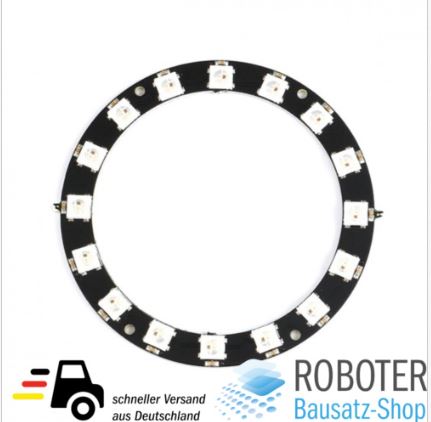
LEDRing
16Bit RGB LED Ring WS2812 5V ähnl. Neopixel für Arduino Raspberry Pi

TM1637 4-Bits Digital Tube LED Anzeige Clock Modul Mit Display Für Arduino


Betriebsspannung: 3.3V - 5,25V
Strom: 30 - 80 mA
4 Bit Anzeige
vier Ziffern, getrennt durch Doppelpunkt
Jede Ziffer und Punkte individuell ansteuerbar
Größe: 47mm x 24mm x 11,5mm
Gewicht: ca. 8g
https://draeger-it.blog/arduino-lektion-26-4-digit-7-segment-display/
Displays
LCD Display


http://www.sprut.de/electronic/lcd/
http://www.14core.com/wiring-i2c-module-on-16x2-lcd-with-sclsda/
OLED
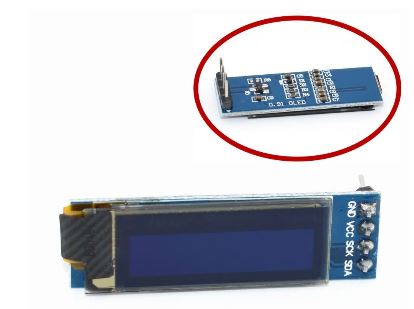
0.91 inch OLED
0.91 inch OLED module 0.91" white/Blue OLED 128X32 OLED LCD LED Display Module 0.91" IIC Communicate for Arduino

TFT
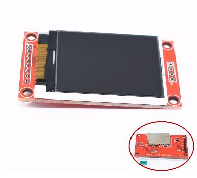
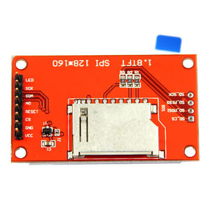
1.8 inch TFT LCD
1pcs 1.8 inch TFT LCD Module LCD Screen SPI serial 51 drivers 4 IO driver TFT Resolution 128*160 TFT interface 1.8 Inch


2.4" 2.4 inch TFT
2.4" 2.4 inch TFT 240*320 LCD Screen Module 5V/3.3V For Arduino UNO R3 Mega2560 Board Support STM32 C51 Micro SD Card ILI9341


SPI
Nokia 5110
For Arduino 84*48 Nokia 5110 LCD White/Blue Display Screen Module Module DIY AHS


http://anleitung.joy-it.net/?goods=lcd-modul-84x48-nokia-5110
Specification:
1. "LIGHT" linked with GND, the backlight to be lit.
2. Need you to compress the screen and PCB tighter, might got loose after the delivery.
3 Use a 3.3V controller, otherwise the display could be quite vague.
LCD5110 Module:
Power supply voltage:2.7V-3.3V,5V is OK,but part of the screen becomes black when tested
Data interface level:2.7-5V
Backlight power supply voltage:highest 3.3V
Installation diameter:2mm
Backlight:White
Document for Download:Data
1.RST--------- reset
2.CE------------chip selection
3.DC-----------data/commands choice
4.DIN-----------serial data line
5.CLK------------serial Clock Speed
6.3.3V------------VCC
7.LIGHT--------- backlight control terminal
8.GND-----------power negative
Features:
84 X 48 dot matrix LCD,can show 4 lines of characters
Use serial interface communicate with the master processor,the number of interface signal line reduced
greatly, only 8 signal lines including power and GND.Support different types of MCU,such as the SPI,
MCS51 serial mode 0 of AVR.Transfer rate up to 4Mbps,can full speed write display data without waiting time.
Can use the conductive glue to connect the module with the printed board,without connecting cable.The
metal hooks on the module can fix the module on the printed board,which is very easy to install and replace.
LCD controller/driver chip has been bound to LCD chip,the volume of LCD is small
Low power supply,the working current in normal situation is lower than 200μA,and has power-down mode.
Blue Backlights White Backlights
Bare Screen(NO PCB)
Controller Philp PCD8544 LCD controller .
input voltage :2.7-3.3v
can be driverd by Arduino/STM32/8051/AVR/PIC and other low power controllers
Compatible with Nokia 3310 LCD driving source code

NOTE:This item is only Nokia 5100 LCD bare screen without PCB pinboard
Package Included:
1*Nokia 5110 LCD Bare Screen 84*48 (NO PCB) for Arduino AVR PIC STM32
ST7735
1.44" Colorful SPI TFT LCD Display ST7735 128X128 Replace Nokia 5110/3310 AHS


Feature:
100% brand new and high Quality
1.44-inch screen with SPI serial backplane module, a minimum of only four IO-driven resolution 128 * 128
Spike NOKIA 5110, perfect upgrade true color
Size: 1.44 inch SPI serial bus
Resolution 128 * 128
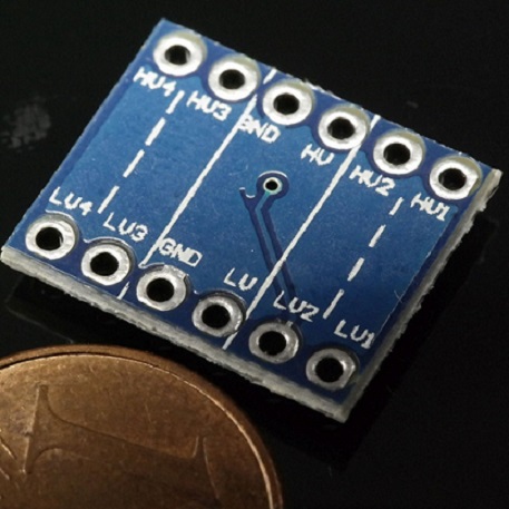
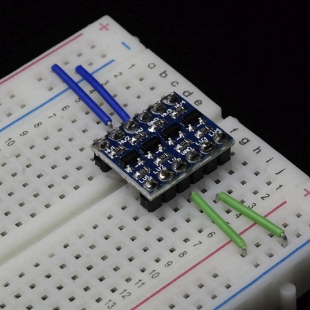
Pegelwandler 5V 3,3V 4Kanal Level Shifter
http://www.ebay.de/itm/172110795634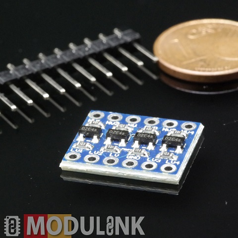


TSOP1136 IR-Empfänger
http://pdf.datasheetcatalog.net/datasheets/restul/305097_DS.pdf
https://learn.adafruit.com/using-an-ir-remote-with-a-raspberry-pi-media-center?view=all
TSOP 4838 IR-Empfänger
Fernbedienung + HX1838 Empfänger + Codiert Infrarot modul


SPI
MCP3008
Analog-Digital Converter

RaspberryPi
http://tutorials-raspberrypi.de/raspberry-pi-mcp3008-analoge-signale-auslesen/
http://erik-bartmann.de/component/attachments/download/21.html
I2C
http://rn-wissen.de/wiki/index.php/I2C_Chip-%C3%9Cbersicht
PCF 8566
Dil-40 LCD-Treiber

PCF 8570
Dip-8 SRAM

PCF 8573
http://datentechniker2004.faxgate.org/ingo.goeppert/dt/projekte/i2c/dateien/pcf8573.pdf
PCF 8574 P I2C Port Expander
Philips I²C-Bus Port-Erweiterung DIP 16.


http://www.ti.com/lit/ds/symlink/pcf8574.pdf

https://www.mikrocontroller.net/articles/Port-Expander_PCF8574
PCF 8582
Dip-8 I²C Bus EEPROM 256 Byte

PCF 8584 I2C-bus Controller
Dil-20 Interface

http://www.nxp.com/documents/data_sheet/PCF8584.pdf
PCF 8591

Dil-16 A/D-Wandler
YL-40 PCF8591 8 Bit Analog-Digital-Wandler ADC I2 C YL-40 Arduino

DS 1620
Thermometer, DIP-8
EEProms 24C02
PN532 NFC RFID
OLED Display

Ein 0,96 Zoll OLED Display I²C mit 128×64 Pixel und ein Arduino
http://blog.simtronyx.de/ein-096-zoll-oled-display-i%C2%B2c-mit-128x64-pixel-und-ein-arduino/
OLED i2c display with arduino
http://www.instructables.com/id/Monochrome-096-i2c-OLED-display-with-arduino-SSD13/?ALLSTEPS
Arduino OLED Display Library
https://oscarliang.com/arduino-oled-display-library/
https://github.com/wtfuzz/ssd1306_text
https://learn.adafruit.com/monochrome-oled-breakouts/overview
https://learn.adafruit.com/monochrome-oled-breakouts?view=all
TM1638 LED&Key

https://blog.3d-logic.com/2015/01/10/using-a-tm1638-based-board-with-arduino/
http://arduinolearning.com/learning/basics/arduino-tm1638-module.php
http://www.arduino-projekte.de/index.php?n=69
https://github.com/rjbatista/tm1638-library/wiki
DS3231 AT24C32 IIC Modul Präzisions-Taktmodul

https://github.com/akafugu/WireRtcLibrary
https://github.com/MrAlvin/RTClib

ZS-042 Real-time Clock Module - Blau DS3231


SRF 08 Ultraschall Abstandssensor


HC-SR04 Ultraschall Abstandssensor

Der HC-SR04 Sensor ist im eigentlichen Sinne kein Abstand/Bewegungsmelder, sondern ein Ultraschallsensor. Durch einen kleinen Trick ist es dennoch möglich Distanzen zu messen. Indem man die Zeit misst, welche zwischen Senden und Empfangen eines Ultraschallsignales vergangen ist, kann man sich die Distanz herleiten, da die Schallgeschwindigkeit in der Luft bekannt ist. Im Tutorial gehe ich sehr detailiert darauf ein. Ein Aspekt der allerdings beachtet werden muss ist der breite Öffnungswinkel: Da der Ultraschall sich nicht nur auf einer Geraden ausbreitet, sondern in einem Öffnungswinkel von ca. 15° wird das Signal als erstes vom nähesten Punkt in diesem Bereich reflektiert – was eben auch ein äußerer Punkt sein kann.
Als grobe Schätzung bzw. für fahrende Roboter eignet er sich dennoch gut, nicht zuletzt wegen den geringen Kosten.
https://tutorials-raspberrypi.de/entfernung-messen-mit-ultraschallsensor-hc-sr04/
Module
MINI L293D Arduino Motorantrieb Erweiterungskarte Mini L293D Motorantrieb Modul

GY-68 BMP180 I2C Digitaler Luftdrucksensor Board

In Wetterstationen und ähnlichen Projekten kann die Bestimmung der Luftdrucks aussagekräftig sein. Dazu verwendet man am besten den BMP180, welcher über I2C am Raspberry Pi angesteuert wird. Neben dem Luftdruck kann auch die Temperatur ausgelesen werden und außerdem die Höhenlage (Altitude). Allerdings ist die letzte Angabe nicht all zu genau. Falls man die Höhe braucht, sollte man lieber die Werte mit einem GPS Empfänger auslesen.
https://tutorials-raspberrypi.de/raspberry-pi-und-i2c-luftdrucksensor-bmp180/
3 in 1 Remote Control + HX1838 Receiver + Coded Infrared Module with Female to Female Dupond Line Wire Cable Free Shipping

HC-SR501 Body Sensor Module Adjust IR PIR Pyroelectric Infrared PIR Motion Human Sensor Detector Module For Arduino

Der PIR Bewegungssensor hat einige Vorteile gegenüber anderen ähnlichen Produkten: Neben dem geringen Preis wird ein Signal erst dann gesendet, sobald sich etwas bewegt. Dadurch kann man auf Signal-Flanken mittels den GPIOs warten. Außerdem kann dabei ein Widerstand variiert werden, sodass nur noch bei nahen Bewegungen ein Signal gesendet wird oder eben bereits weit entfernte Änderungen wahrgenommen werden.
Neben Außenbereich-Projekten kann der PIR auch wunderbar in Gebäuden verwendet werden – sei es zum Aktivieren der Beleuchtung oder, wie ich es verwende, zum Einschalten meines Touchscreens zur Hausautomatisierung sobald jemand sich ihm nähert.
https://tutorials-raspberrypi.de/raspberry-pi-bewegungsmelder-sensor-pir/
BV4221
USB nach I2C
RS232-TTL
HC-05


https://www.itead.cc/wiki/Serial_Port_Bluetooth_Module_(Master/Slave)_:_HC-05
ftp://imall.iteadstudio.com/Modules/IM120723009/DS_IM120723009.pdf
https://www.az-delivery.de/blogs/azdelivery-blog-fur-arduino-und-raspberry-pi/hc-05-bluetooth-modul-einfuhrung?ls=de&cache=false
https://howtomechatronics.com/tutorials/arduino/arduino-and-hc-05-bluetooth-module-tutorial/
http://shelvin.de/das-bluetooth-modul-hc-05-mit-at-kommandos-vom-arduino-programmieren/
https://exploreembedded.com/wiki/Setting_up_Bluetooth_HC-05_with_Arduino
https://exploreembedded.com/wiki/images/a/a5/HC_05_Core_Datasheet.pdf
http://www.rasmicro.com/Bluetooth/EGBT-045MS-046S%20Bluetooth%20Module%20Manual%20rev%201r0.pdf
https://www.itead.cc/wiki/Serial_Port_Bluetooth_Module_(Master/Slave)_:_HC-05
https://igniteinnovateideas.wordpress.com/2016/04/18/arduino-bluetooth-basic-tutorial/

https://arduino-hannover.de/2013/07/20/bluetooth-kochbuch-fur-arduino/
https://forum.arduino.cc/index.php?topic=544399.0
https://draeger-it.blog/android-bluetoothkommunikation/
BlueSmirf
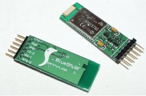

http://www.lynxmotion.com/images/html/build125.htm
http://www.electronics123.net/amazon/datasheet/RN-41.pdf
https://learn.sparkfun.com/tutorials/bluetooth-basics
http://ww1.microchip.com/downloads/en/DeviceDoc/rn-41-ds-v3.42r.pdf
https://www.digikey.com/eewiki/display/Wireless/Getting+Started+with+RN42+Bluetooth+Module
https://www.sparkfun.com/datasheets/Wireless/Bluetooth/rn-bluetooth-um.pdf
https://www.multitech.com/documents/publications/manuals/s000360i.pdf
http://www.cse.dmu.ac.uk/~eg/tele/sonyat.pdf
https://www.sparkfun.com/datasheets/RF/BlueRadios_AT_Commands_Rev_2.8.1.4.0.pdf
http://www.spezial.cz/pdf/Serial_Port_Adapter_AT_Commands.pdf
http://www.blueradios.com/software_SmartPhoneApps.htm
RFM12
Tastenfeld
Arduino Keypad Pinout
http://premiumandroid.com/2019/01/27/arduino-keypad-pinout/
3x4

MULTICOMP MCAK304NBWB Tastenfeld, 20 mA, 24 V, 3 x 4, Matrix, 12
The MCAK304NBWB is a 3 x 4 matrix plastic keypad.
•Actuating force of 100 ±30g
•Contact rating of 20mA at 24VDC
•Maximum contact resistance of 200 ohm
•10,00,000 cycles per key life
•Operating temperature range -20°C to +60°C
http://learning.grobotronics.com/2014/03/read-keypad-arduino-i2c/
http://playground.arduino.cc/Main/KeypadTutorial
http://playground.arduino.cc/Main/I2CPortExpanderAndKeypads
https://z4ziggy.wordpress.com/2014/06/13/arduino-keypad-with-1-analog-pin/
TTP224 4 Schlüssel Buttons Touch-Switch-Modul Touch-Kapazität Digital-Wandler Vorstand Sensor 2,4V-5,5V

TTP226 8-Kanal-kapazitiver Schalter Digital Touch Sensor Board-Modul für Arduino

TTP229 16-Channel Digitaler Touch Kapazitiver Sensor Modul XD-62B TTP229

Arduino

https://github.com/arduino12/ttp229-arduino
4x4

Folientastatur mit i2C Portexpander PCF8574
https://www.bastelgarage.ch/index.php?route=extension/d_blog_module/post&post_id=8
ESP Easy Tastatur und PCF8574
https://www.letscontrolit.com/forum/viewtopic.php?t=3845
I2C

Sensoren
50 DER WICHTIGSTEN RASPBERRY PI SENSOREN UND MODULE
http://tutorials-raspberrypi.de/raspberry-pi-sensoren-uebersicht-die-50-wichtigsten-module/
Infrared Reflective Photoelectric Switch TCRT5000 Ir Barrier Line Track Senso io

YL-40 PCF8591 8 Bit Analog-Digital-Wandler ADC I2 C YL-40 Arduino
Luftdruck HP03S I2C
http://digitalradiomondiale.blogspot.de/2012/06/hp03s-luftdruck-temperatursensor-mit.html
http://spurtikus.de/basteln/datalogger/

Luftfeuchte HH10D
https://tushev.org/articles/arduino/6/interfacing-hh10d-with-arduino

DHT11 / DHT22 AM2302
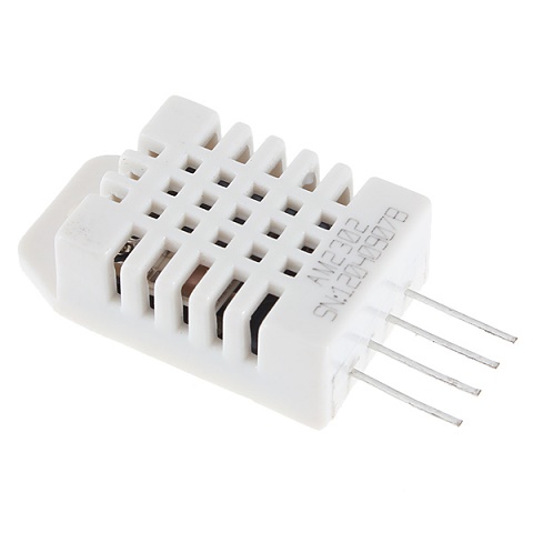

Die Sensoren DHT11 und DHT22 können neben der Temperatur auch die Luftfeuchtigkeit messen. Dabei wird nur ein GPIO belegt. Der Unterschied zwischen beiden ist vor allem die Messweite und die Genauigkeit. Der weiße DHT22 kann alle Luftfeuchtigkeitsbereiche von 0-100% messen und hat dabei eine Genauigkeit von 2%. Im Vergleich sind mit dem DHT11 (blau) lediglich Bereiche von 20-90% Luftfeuchte messbar, aber vor allem die Genauigkeit ist mit 5% deutlich schlechter. Einzig preislich hat der hellblaue DHT11 Sensor einen kleinen Vorteil (ca. einen Euro).
Arduino
https://github.com/nethoncho/Arduino-DHT22

http://www.buildcircuit.com/arduino-and-am2302-dht22-on-a-mini-breadboard/
http://www.arduino-tutorial.de/2014/01/temperatur-und-luftfeuchtigkeit-messen/
http://www.dfrobot.com/wiki/index.php/DHT22_Temperature_and_humidity_module_SKU:SEN0137
https://arduino-info.wikispaces.com/DHT11-Humidity-TempSensor
https://arduino-info.wikispaces.com/TemperatureHumidity

Raspberry Pi
https://tutorials-raspberrypi.de/raspberry-pi-luftfeuchtigkeit-temperatur-messen-dht11-dht22/
http://christian-ohmer.de/page/wiki/doku.php?id=wiki:sensoren:dht22
https://www.sweetpi.de/blog/436/luftfeuchtigkeit-und-temperatur-mit-dem-raspberry-pi-messen
https://klenzel.de/1827
http://wiki.volkszaehler.org/dht22
https://www.sweetpi.de/blog/436/luftfeuchtigkeit-und-temperatur-mit-dem-raspberry-pi-messen

GY-68 BMP180
BMP180 Digitaler Luftdruck Sensor GY-68 BMP085 Arduino Raspberry Barometer Modul

Technische Daten:
IC: BMP180
Betriebsspannung: 1,8V - 3,6V
Interface: I2C
Reaktionszeit: 7,5 ms
Stromverbrauch: 5µA, Standby: 0,1µA
Größe: ca. 14 mm x 12 mm
Gewicht: ca. 1,27 g
Beim BMP180 handelt es sich um einen digitalen und sehr präzisen Temperatur- und Luftdrucksensor. Er ist wesentlich genauer als sein Vorgänger BMP085 und eignet sich auf Grund seines niedrigen Stromverbrauchs bestens zur mobilen Anwendung.
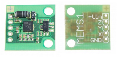
3 Achsen Beschleunigung MEMS1

GY-521 3 Achsen MPU-6050 Beschleunigungssensor / Gyroskop / Accelerometer
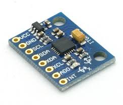


https://tutorials-raspberrypi.de/raspberry-pi-mpu-6050-rotationssensor-webgl-nodejs-server/
https://www.hackster.io/Nicholas_N/how-to-use-the-accelerometer-gyroscope-gy-521-6dfc19
X9C103S Digital Potentiometer Board Module DC3V-5V for Arduino 10K Span Potentiometer


Kompassmodul HDMM01
http://www.mtahlers.de/index.php/elektronik/sensoren/mmc2120mg
http://www.aurob.com/?p=467
http://chris.cnie.de/avr/arduino-hdmm01.html

Flexsensor 2.2

CODE
#include <Servo.h>
Servo myservo; // create servo object to control a servo
int potpin = 0; // analog pin used to connect the potentiometer
int val;// variable to read the value from the analog pin
void setup()
{
Serial.begin(9600);
myservo.attach(9); // attaches the servo on pin 9 to the servo object
}
void loop()
{
val = analogRead(potpin);
between 0 and 1023)
Serial.println(val);
val = map(val, 50, 300, 0, 179);
and 180)
myservo.write(val);
value
delay(15);
}
// reads the value of the potentiometer (value
// scale it to use it with the servo (value between 0
// sets the servo position according to the scaled
// waits for the servo to get there
37-IN-1-SENSOR-KITS-FOR-ARDUINO

http://de.aliexpress.com/item/37-IN-1-SENSOR-KITS-FOR-ARDUINO-HIGH-QUALITY-FREE-SHIPPING-Works-with-Official-for-Arduino/32649847420.html#extend
Arduino
https://www.elektor.de/arduino-sensor-kit
RaspBerryPi
http://tutorials-raspberrypi.de/raspberry-pi-gas-sensor-mq2-konfigurieren-und-auslesen/
KY-001 DS18B20

Temperature Sensor Module DS18B20
This module measures the temperature and reports it through the 1-wire bus digitally to the Arduino.
Einen sehr einfachen Sensor stellt der DS18B20 bzw. DS18S20 dar. Diese Raspberry Pi Sensoren werden über den sog. 1-Wire Bus angesprochen. Ein Vorteil besteht darin, dass viele verschiedene 1-Wire Bauteile hintereinander angeschlossen werden können und mittels eines einzigen GPIOs ausgelesen werden. Allerdings können diese Module keine zusätzlichen Infos wie Luftfeuchtigkeit und/oder Luftdruck messen. Dafür eignet sich der DS18B20 besonders im Außenbereich, da es auch wasserfeste Versionen zu kaufen gibt. Mit einem Messbereich von -55°C bis +125°C ist er selbst für nicht alltägliche Anwendungen gut geeignet.
https://tkkrlab.nl/wiki/Arduino_KY-001_Temperature_sensor_module
https://tutorials-raspberrypi.de/raspberry-pi-temperatur-mittels-sensor-messen/


KY-002
Shock Sensor Module
This module is digital shock sensor. It will output a high level signal when it detects a shock event.

KY-003

Hall Magnetic Field Sensor Module
This module can be used to detect the presence of an magnetic field. If there is an magnetic field present, it will report a high level signal.
KY-004 Button
Momentary Button Module
This is a button module. When the button is pressed, it will a high level signal.

KY-005
Infrared Transmitter Module
This is an infrared transmitter module that is used to emit infrared signal.

KY-006 Buzzer
Buzzer Module
This is an active buzzer module that can make different sound.

YL-44
Buzzer Module


KY-007
KY-008 Laser
Laser Diode Module
This is a laser emitter diode. The working voltage is 5V, with a wavelength of 650nm.

KY-009 3C LED
3-color full-color LED SMD modules

KY-010
Optical broken module

KY-011
2-color LED module

KY-012

KY-013

KY-014
KY-015 Temp/Hum

KY-016

KY-017

KY-018 FotoR

KY-019 Relay

KY-020

KY-021

KY-022

KY-023

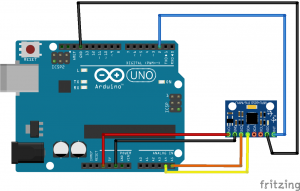
KY-024 Linear magnetic Hall Sensor
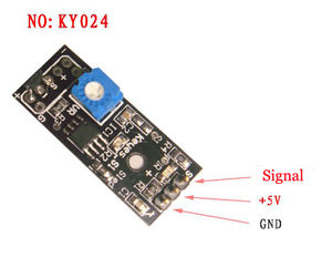

http://sensorkit.joy-it.net/index.php?title=KY-024_Linear_magnetic_Hall_Sensor
KY-025

KY-026

KY-027

KY-028

KY-029
KY-030
KY-031

KY-032

KY-033

KY-034

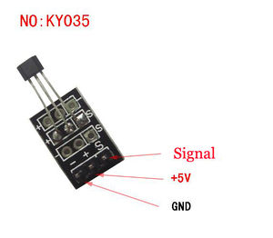
KY-035
KY-035 Bihor magnetic sensor module

KY-036

KY-037

KY-038

KY-039

KY-040 Rotary Encoder
http://henrysbench.capnfatz.com/henrys-bench/arduino-sensors-and-input/keyes-ky-040-arduino-rotary-encoder-user-manual/

WIKI
https://tkkrlab.nl/wiki/Arduino_37_sensors
http://linksprite.com/wiki/index.php5?title=Advanced_Sensors_Kit_for_Arduino
Gas Sensoren MQ

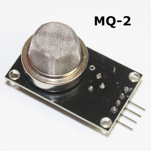
MQ-2
MQ-2 Sensitive for Methane, Butane, LPG, smoke. This sensor is sensitive for flamable and combustible gasses.

https://blog.moneybag.de/gassensor-mq-7-mit-lcd-display-und-arduino-nano/
Die MQ Gas Sensoren können verschiedene Gase bei Raumtemperatur erkennen. Je nach Modell werden andere Gase unterstützt. Der übliche MQ-2 Sensor kann Methan, Butan, LPG und Rauch erkennen, der MQ3 erkennt bspw. Alkohol, Ethanol und Rauch, usw. Eine Auflistung aller MQ Sensoren und deren unterstützte Gase kann hier (deutsch bzw. englisch) eingesehen werden.
Es sollte dabei darauf geachtet werden, dass diese Sensoren sehr heiß werden können und man sie daher nicht direkt anfassen sollte. Da diese Module auch analog mit 5V arbeiten, ist auch hier ein MCP3008 sowie ein 3.3V-5V TTL zum Auslesen der Signale nötig.
https://tutorials-raspberrypi.de/raspberry-pi-gas-sensor-mq2-konfigurieren-und-auslesen/
MQ-3
MQ-3 Sensitive for Alcohol, Ethanol, smoke

MQ-4
MQ-4 Sensitive for Methane, CNG Gas

MQ-5
MQ-5 Sensitive for Natural gas, LPG

MQ-6
MQ-6 Sensitive for LPG, butane gas

MQ-7
MQ-7 Sensitive for Carbon Monoxidehttps://blog.moneybag.de/gassensor-mq-7-mit-lcd-display-und-arduino-nano/
MQ-8
MQ-8 Sensitive for Hydrogen Gas

MQ-9
MQ-9 Sensitive for Carbon Monoxide, flammable gasses.

MQ-135
MQ-135 For Air Quality. Sensitive for Benzene, Alcohol, smoke.

http://playground.arduino.cc/Main/MQGasSensors
https://disqus.com/home/discussion/mysensors/mysensors_gas_sensor_89/
https://community.particle.io/t/mq135-and-spark-core/12657
https://github.com/empierre/arduino
https://github.com/empierre/arduino/blob/master/AirQuality-MQ135.ino
https://gleisnetze.de/2015/12/25/das-erste-kleine-programm/
https://gleisnetze.de/2016/02/06/sensor/
https://www.mysensors.org/build/gas
Links
http://de.aliexpress.com/store/product/for-Arduino-Diy-Starter-1set-Gas-Detection-Sensor-Module-MQ-Kit-MQ-2-MQ-3-MQ/1757110_32349408775.html
http://playground.arduino.cc/Main/MQGasSensors
https://blog.moneybag.de/gassensor-mq-7-mit-lcd-display-und-arduino-nano/
http://www.instructables.com/id/How-to-use-MQ2-Gas-Sensor-Arduino-Tutorial/?ALLSTEPS

http://www.instructables.com/id/How-to-use-MQ2-Gas-Sensor-Arduino-Tutorial/
http://www.seeedstudio.com/wiki/How_to_choose_A_Gas_Sensor
https://blog.moneybag.de/gassensor-mq-7-mit-lcd-display-und-arduino-nano/
https://github.com/empierre/arduino/blob/master/AirQuality-MQ135.ino
http://davidegironi.blogspot.de/2014/01/cheap-co2-meter-using-mq135-sensor-with.html#.V7hyrE3wC9I
https://forum.mysensors.org/topic/147/air-quality-sensor
Pulsesensor

http://de.aliexpress.com/store/product/Free-shipping-pulsesensor-pulse-heart-rate-sensor-for-Arduino-open-source-hardware-development-pulse-sensor/1280487_32582700771.html?storeId=1280487
http://pulsesensor.com/
Raspberry Pi
http://tutorials-raspberrypi.de/raspberry-pi-puls-herzfrequenz-messen/
Sensormodul Regen Wetter Modul

Feuchtigkeitssensor

Dieser analoge Feuchtigkeitssensor findet einen hervorragenden Platz in automatischen Bewässerungssystemen. Dabei wird er in die Erde gesteckt und misst die Feuchtigkeit, indem zwischen den Strängen ein Strom fließt. Umso feuchter die Erde dazwischen ist, umso höher ist das (analoge) Signal. Um den Wert mit dem Raspberry Pi auslesen zu können, wird noch der MCP3008 benötigt (Arduinos können analoge Signale direkt erkennen).
https://tutorials-raspberrypi.de/bodenfeuchtigkeit-mit-dem-raspberry-pi-messen/
SHARP IR Ranger Sensor GP2D12
Introduction

The Sharp GP2D12 is an analog distance sensor that uses infrared to detect an object between 10 cm and 80 cm away. The GP2D12 provides a non-linear voltage output in relation to the distance an object is from the sensor and interfaces easily using any analog to digital converter.
Specification
- Measuring range : 10 to 80 cm
- The maximum allowable Angle : > 40 °
- The power supply voltage : 4.5 to 5.5 V
- The average power consumption : 35 mA
- Peak power consumption : about 200 mA
- The frequency of updates/cycle : 25 Hz/40 ms
- Analog output noise : < 200 mV
Document
Pinout

Usage
Here is the guide illustrates how to connect an Arduino to the ADXL335 breakout board.


Example code
char GP2D12;
char a,b;
void setup()
{
 Serial.begin(9600); //
}
void loop()
{
 int val;
 GP2D12=read_gp2d12_range(0);
 a=GP2D12/10;
 b=GP2D12%10;
 val=a*10+b;
 if(val>10&&val<80)
 {
   Serial.print(a,DEC);//
   Serial.print(b,DEC);//
   Serial.println("cm");//
 }
 else Serial.println("over");//
 delay(50);
}
float read_gp2d12_range(byte pin)
{
 int tmp;
 tmp = analogRead(pin);
 if (tmp < 3)return -1;
 return (6787.0 /((float)tmp - 3.0)) - 4.0;
}
How to buy
Click here to buy SHARP IR Ranger Sensor GP2D12
Fingerprint Sensor


Color: Black + green
Material: Plastic + component
Working frequency: 433Mhz/868Mhz/915Mhz
Sensitivity: -100dBm
Working voltage: 1.9~3.6V,
Operating rate: 50Kbps,
Supply voltage: DC 3.6~6.0V
Character file size:256 bytes
Template size:512 bytes
Storage capacity:1000
Search time: < 1 second
False Acceptance Rate (FAR) < 0.001%
False Rejection Rate (FRR) < 1.0% (security level: 3)
Voltage 3.6-6.0V DC via USB port
Working current: < 120mA
Peak voltage: < 140mA
Window size: 14 x 18mm
Upstream: UART: (9600×N)bps (N=1~12, N default 6, equal 57600bps)
Operating environment Temperature: -20 to 50 centigrades
Relative humidity: 40%RH to 85%RH (No condensation)
During the fingerprint verification process, the latest collected fingerprint features would be integrated into the fingerprint database automatically so that the users would  obtain better and better fingerprint verification result.
Can be embedded into a variety of end products, such as: access control, attendance, safe, car door locks.
Arduino Lib
https://github.com/adafruit/Adafruit-Fingerprint-Sensor-Library

Tutorial
https://learn.adafruit.com/adafruit-optical-fingerprint-sensor
https://learn.adafruit.com/adafruit-optical-fingerprint-sensor/downloads
https://learn.adafruit.com/adafruit-optical-fingerprint-sensor/enrolling-new-users-with-windows
GP2Y1014AU0F Compact Optical Dust Sensor


http://arduinodev.woofex.net/2012/12/01/standalone-sharp-dust-sensor/
http://qqtrading.com.my/optical-dust-sensor-gp2y1010au0f-sharp
Spannungsversorgungen
DC 5-24V to Dual Power ±12V ±5V +3.3V Boost USB Linear Regulator Module DIY Kit
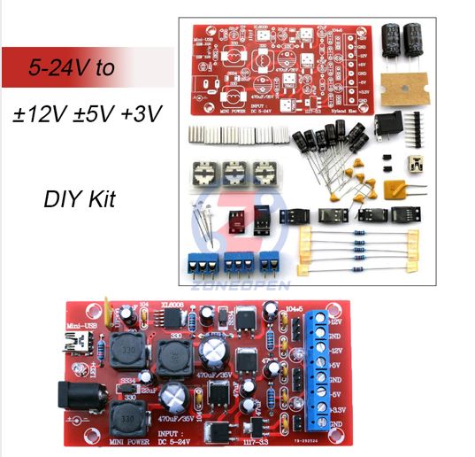

Features:
Product title marked ""DIY kit"" are parts, need your own soldered assemblies, to demonstrate the convenience, the main products of the physical map soldering is completed, the second figure is all the parts that you receive, be sure to pay attention to distinguish
Circuit performance:
This circuit is a wide range by a single power supply input (5-24V, such as the output current is small, use 3.7V lithium batteries as input, can also provide normal output, Converted to multiple positive and negative regulated output converter, Most electronic required to meet the test, Single wide range input voltage, you can access USB, the input with limiting protection.
Input voltage: 5-24V DC
Output voltage: + 12V, -12V, + 5V, -5V , +3.3V.
Output current: 300mA (per channel)
This circuit is a wide range by a single power supply input (5-24V, such as the output current is small, use 3.7V lithium batteries as input, can also provide normal output), is converted to multiple positive and negative regulated output converter to meet the most desired electronic experiments, small, easy to use, since you can get rid of a heavy large power supply, convenient to carry out a variety of experiments
XL6008

https://datasheetspdf.com/pdf-file/839861/Xlsemi/XL6008/1
78Mxx

78M05
78M12
79Mxx

79M05
79M12
AMS 117-3.3

Spannungsversorgung 5V/3,3V
Power
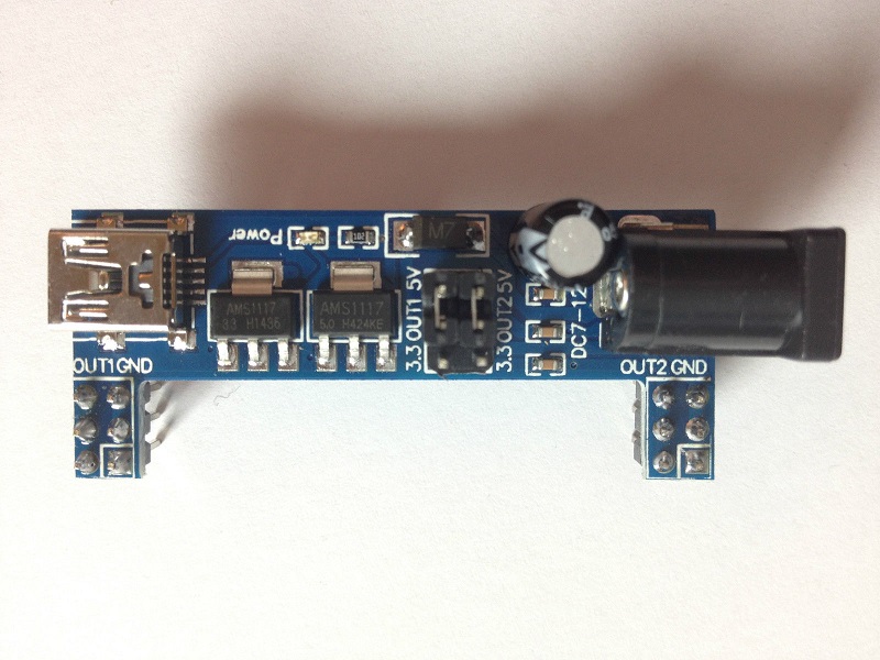

Steckbrett Spannungsversorgung
•Für MB102 Steckbretter
•Versorgung über USB Mini oder 7-12V DC
•Beide Terminals können separat mit 0V; 3,3V oder 5V belegt werden
•Max output: <700mA
MB102
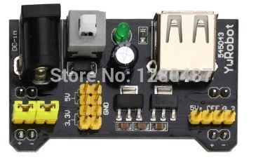 Breadboard stromversorgungsmodul, kompatibel mit 5 V, 3,3 V
gelten MB102 breadboard
eingangsspannung: 6,5-12 V (DC) oder usb-netzteil
ausgangsspannung: 3,3 V/5 V kann über
maximale ausgangsstrom: < 700 ma
fluktuation zwei straße unabhängige steuerung, kann über zu 0 V, 3,3 V, 5 V
auf-bord zwei gruppen von 3,3 V, 5 V DC ausgang stecker pin
Breadboard stromversorgungsmodul, kompatibel mit 5 V, 3,3 V
gelten MB102 breadboard
eingangsspannung: 6,5-12 V (DC) oder usb-netzteil
ausgangsspannung: 3,3 V/5 V kann über
maximale ausgangsstrom: < 700 ma
fluktuation zwei straße unabhängige steuerung, kann über zu 0 V, 3,3 V, 5 V
auf-bord zwei gruppen von 3,3 V, 5 V DC ausgang stecker pin

TSP 03

AC-DC 220 V zu 3,3 V
TSP 05

AC-DC 220 V zu 5 V
5V 700mA 3.5W


AC-DC 5V 700mA 3.5W Precision Buck Converter AC 220v to 5v DC step down Transformer power supply module for Arduino
2PCS Ultra-small LM2596 power supply module DC / DC BUCK 3A adjustable buck module regulator ultra LM2596S 24V switch 12V 5V 3V

Mini Buck Step Down Converter DC-DC 1.2V 2.5V 3V 3.3V 5V Power Supply Module
.jpg)
Version 4:
1.Model: AMS1117-3.3V
2.Input voltage: DC 4.75V-8V (The input voltage must be over 1V above the output voltage)
3.Output voltage: DC 3.3V/800mA (The load current can not exceed 800mA)
4.PCB size: 20mm*10mm
AC 220V 230V to DC 3.3V 5V 9V 12V Step Down Converter Board Power Supply Module
.jpg)